![]() Перевести
эту страницу на русский язык
Перевести
эту страницу на русский язык
My first oscilloscope: a simple, but still workable instrument.
Of course, and there is no doubts, that the oscilloscope is the most versatile and useful tool by any kind of radiotechnical work. By using this instrument, you may visually observe the signals in your construction, make a conclusions about their frequency and spectral constitution, locate the points of distortion and much, much more.
While I am writing this text, all boards of my new oscilloscope are lying on my table. They were made according to one industrial design with some little modifications. This unit works quite good, having a bandwidth of input signal up to 20 MHz.
But it is rather complicated device, and here i want to describe my old design, which really helped me in many situations to tune many and many circuits. Though its parameters and service are incomparable with those of my new design, and of course, with those of modern expensive instruments, it is really useful. If you want, you may go to the new page, which describes my new oscilloscope too - it is rather complicated, but very easy to assemble as any industrial design.
Why did i make it?
The story of its creation was rather unusual: one day, when i was about 14 years old, my father got somewhere on his job an old box with a CRT (catode-ray tube). I turned it on and saw, that it was just a piece of crap - nothing worked properly, except, i think, CRT. When i realized, that i could not use it as a scope, i put it far away and forgot for several years......
After a plenty of time, i grew up and decided to use this box somehow. There was some tube-based schematics inside, but i had neither experience, nor desire to find out, what it was. I just decide to make my own schematics, retaining only a case and a CRT feeding circuits, and after some experiments, this old box became a 'second life' with a new, transistor-based schematics. Since that moment, i use it.
Some general things about the oscilloscope and oscillography: how does it work
First of all, the oscilloscope is the instrument, which allows to monitor the shape of electrical signals, to show the plot of the monitored signal in time domain. Also, there are a lot of specific oscilloscope applications, for example measurement of relative frequency and phase of two signals. I would advice to anybody, who would like to read indeed VERY good material about the PRACTICAL usage of the scope, to visit Harry's homebrew site, and on this page i will write about the typical electrical structure of the oscilloscope, about some practical circuits and synchronization principles. IF YOU DO NOT WANT TO READ THIS, GO DIRECTLY TO THE CONSTRUCTION DESCRIPTION.
Any oscilloscope has at least two independent channels, called 'X'-channel and 'Y'-channel, according to conventional names of axes in Decart's coordinate system. I say 'at least', because many advanced instruments have additional 'Z' channel, which controls the beam intensity and therefore the brightness. Also, there are two beam instruments, which have two identical 'Y' channels.
1) 'Y' channel (signal channel)
Y-channel consists on the input attenuator, signal preamplifier and final signal amplifier.
How signals of different amplitudes and frequencies are normalized (scaled) for proper viewing: frequency-compensated attenuators.
First of all, the monitored signal goes to the input attenuator, which can reduce it's amplitude in 10, 100 or 1000 times or leave it without changes depending on the 'sensitivity' switch position. Usually 'sensitivity' switch has the values 0.01 , 0.02, 0.05, 0.1, 0.2, 0.5, 1 etc. Volts/division and a big number of them causes some difficulties in providing necessary correction of the amplification by one switchable attenuator. Therefore, in many instruments initial changing of signal level is performed by the resistive attenuator, and further correction in 2 or 5 times is done in subsequent stages, usually by the change of negative feedback value. The attenuator must have flat frequency response and equal input impedance and reactance on all positions. Usually, the input impedance is 1 MOm, and the reactance lies between 20 and 40 pF.
Typical resistive attenuator, as shown on figure 1, consists on two resistors, and the division coefficient is determined as k=R1/(R1+R2). But in real situations, the attenuator is connected to the particular loading and it can can affect the division coefficient. If the internal resistance of the loading is comparable to the R2 value, k becomes higher, than the value of unencumbered attenuator. If you look at figure 2, it becomes quite reasonable: internal resistance of the loading is connected in parallel to R2, and k becomes equal to R1/(R1+R2+Rload).
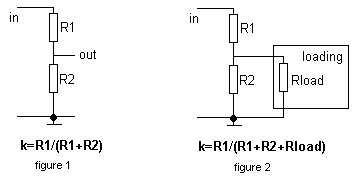
Therefore, to ensure 'theoretical' k, the first rule is: Rload must be much greater, than R2.
Everything written above was true for the DC currents and low-frequency operations, where contribution of capacities are low and negligible. But the oscilloscope, as well as many other control equipment, must be able to work with the wide spectrum of frequencies, and the frequency response must be as flat as possible. Any loading, regardless to the nature has its own internal capacity. And on high frequencies, the reactance of this capacity becomes comparable with value of R2. The division coefficient becomes larger with the increase of the frequency, causing non-linear frequency response with a fall down at higher frequencies . To compensate the influence of the internal capacity of the loading, an additional capacitor should be set in parallel to R1 and because the reactance is proportional to C-1(C - capacity), its value is determined from equation: R1/R2 = Cload/C1 . Only in this case the division coefficient is equal for all frequencies. If value of C1 is smaller, than optimal, there is a fall down of frequency response on higher frequencies, and if it is greater - division coefficient decreases with the frequency (figure 3).
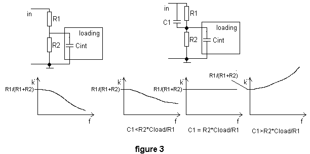
Showed on the figure very simple schematics is so called frequency-compensated attenuator. Such device is widely used in many control equipment and anywhere for decreasing the signal's amplitude without change of its spectrum (and therefore, the shape).
This simple design is quite practically workable, but it has one serious disadvantage: If the division coefficient becomes rather high (say, 100, which is quite typical value), the required capacity of C1 becomes too small to be achievable, because any circuit implementation has an internal capacity in parallel to R1, which may be greater than required value of C1. To add to this, input reactance of such type of attenuator depends on the division coefficient, which is not very good, if the attenuator serves as an input circuit of control device, such as a oscilloscope.
The attenuator design, which is free of the disadvantages mentioned above and which is widely used in control equipment, is presented on the figure 4.
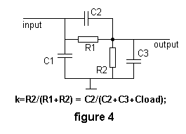
Here we see almost the same design as on the previous figure, but extra capacitors C1 and C3 are added. The first one is quite optional, it is set parallel to the input and serves for the adjusting of the input reactance. C3 and C3 form a capacitive attenuator, which should have the same division coefficient as the resistive one (formed by R1 and R2). With the increase of division coefficient C2 remains the same, but C3 increases. Typical value for division coefficient 10, 100 and 1000 are shown in the table below
|
|
|
|
|
|
|
|
|
|
|
|
|
|
|
|
|
|
|
|
|
|
|
|
|
|
|
|
How signals are amplified: some words about differential amplifiers.
After the attenuator, the input signal goes to the wide-band amplifier, which is usually made according to the differential, or paraphase scheme. The amplifier of similar design is used also in X-channel to amplify the signal of the sweep generator.
An 'ideal' differential amplifier is the device, which has two inputs and two outputs, and which works according to the equation : Uout1-Uout2 = k(Uin1-Uin2); where Uout - voltage on the output, Uin - on the input, k - amplification coefficient. In the ideal case, the maximal absolute value of the output signal is equal to the power supply voltage. But it should be noted, that Uout1-Uout2 may be both of negative and positive signs. Therefore, amplitude of maximal undistorted signal is a power supply voltage multiplied by 2. It is twice more, than corresponding ideal value for a non-differential device. Real differential amplifiers are limited by different excitation processes and can't provide idealized output signal amplitude, but in any case they have doubled output voltage compared to that by non-differentional design with the same power supply.
The next advantage of differential design is a simple achievement of high linearity, which is very difficult to achieve in 'one-shoulder' stages. This is rather simple to rationalize: the schematics of any differential stage has a symmetrical design, consisting on two identical halves, and non-linearity of single 'halve' is partially (or even completely) compensated by the similar non-linearity of the second part of the stage, since the absolute voltages on the outputs of the stage usually don't matter, only the difference between them do.
Next, differential design of the amplifier with one grounded input allows simple adjustment of DC voltage at the output without any significant affecting of characteristics. This is done by following way:
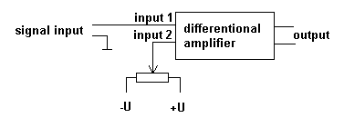
It should be noted, that here the control element (variable resistor) does not bear a amplified signal, it just changes the DC voltage at one of the inputs. Such circuits, which eliminate the necessity to pass the signal through controls are often called a 'COLD CONTROL' schematics. It eliminates many problems, which usually arise, if you pass the high-frequency signals through controls mounted on the front panel. You may place the board and its control elements on any distance between each other without worrying about parasitic influences.
A typical simple differential stage is presented on the picture below:
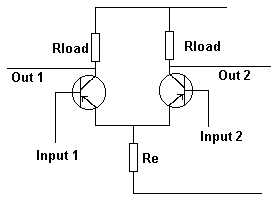
This is the simplest design and is usually modified by different ways to fit real purposes. Some more complicated, but useful stage design is presented on the next picture.
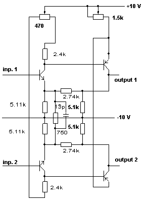
This stage is used in a 'Y' amplifier of my new scope, based on the industrial design. It has very flat frequency response in range up to 30 MHz, and may be even more. Two stages have symmetrical design, and for the correction of parameters mismatch, potentiometer is introduced ito the collector circuit of first stage. 2.74k resistors provide a negative feedback, and frequency-depended positive feedback is formed by RC-circuit in the first stage. The gain is not very high, but usually wide band amplifiers contain many stages to provide necessary overall gain, since there is a rule:
typically, the higher gain has the stage, the lower is its upper working frequency.
Therefore, stages in wide band amplifiers have strong negative feedback and no more, than 10 dB of gain.
Real 'Y'-amplifiers of the scopes are divided into two parts. The first one is preamplifier, which amplifies the signal up to several volts, and the final amplifier, which brings the signal level up to 100-200 V (!), required by the CRT. The latter usually requires additional power supply and use of high-voltage transistors.
2) 'X'-channel (sweep channel).
'X' channel is more complicated, compared to the signal channel. Typical structure of it may be represented as follows:
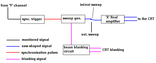
The monitored signal is picked from the 'Y' channel and routed to the synchronization trigger. This block consists usually on the additional amplifier with variable gain and the simple Schmitt-type trigger. The task of the sync. trigger is to form rectangular pulses from the monitored signal, allowing the user to set manually the threshold and polarity of synchronization. Some instruments have additional possibility of 'external' synchronization. In this mode, the signal to the trigger goes from separate input.
Principles of synchronization
The synchronization of channels in the scope serve to make the image on the screen stable. The main rule of the oscillography is:
Only in this case the image will be stable. This is easily understandable: if the k is not integer, any new sweep will start at different phase of the monitored signal. If the frequencies are not very high, for example below 100 Hz, you will see, that image is moving in horizontal direction. In this case you can slow down and even stop it by manual adjusting the sweep frequency. But on higher frequencies independent work of the sweeper makes the signal observing impossible. That is why the circuit is required, which will automatically adjust the sweeper frequency to the nearest integer k value.
On a saw-shaped signal, which is generated by the sweeper, there are two principal ways to change the frequency: changing the rising speed (slope) of the signal by constant amplitude and changing the amplitude by retaining the slope. In the oscilloscope, the slope of the sweep signal is responsible to the time scale and is calibrated to provide time measurements. That is why, it can not be changed. The amplitude of the sweep signal is responsible for the width of the picture, and since it is always greater, than screen's size, it can be changed in a moderate limits.
The synchronization is working by the following way: when the pulse from the sync. trigger comes, the generation of the current saw-wave is terminated, and the new wave starts. But it were so simple, the sweeper frequency would be always equal to the monitored signal frequency. It would cause the image to consist on only one period of monitored wave, which is too inconvenient. To prevent this, as well to prevent the image from getting very small due to very fast sweeper termination, so called 'reset threshold' is introduced. It means, that the saw-wave can be terminated only after it has risen beyond some level, for example beyond 80% of maximal amplitude. 80% is a typical value, which provides stable synchronization and good image (If this level is closed to 100%, only small correction of sweeper frequency can be made causing instability of image in many cases). The principle described here is illustrated on the picture below:
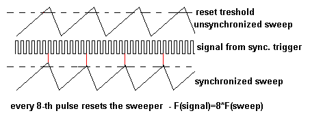
It should be noted, that the sweep frequency must be always smaller or equal to the signal frequency. If the sweeping is too fast, the following thing will occur: in many cases there will be NO appropriate signal from the sync. trigger, when the sweep signal rises from the reset threshold up to maximum value. Therefore, many sweeps will remain unsynchronized, and this will cause effect of 'many pictures on one screen' or just an unstable image at all.
But sometimes it would be useful to make the sweep fast, if you want to look at your signal (ot even on its part) in details. For such purposes serves so-called 'waiting' sweep.
Automatic and 'waiting' sweep.
In the previous section it has been assumed, that the sweep generator produces the continuos saw-shaped signal. This is suitable for most applications, but not for the all.
Imagine, that you have a signal, which consists from short (~1 microsecond) pulses, which are going with period of 1 ms, and you want to look precisely at these impulses in order to examine their shape and duration. The frequency of such signal is about only 1 KHz, so you can't set the sweeper frequency higher to provide stable and clean image. In this case, the sweep speed will be about 1 ms/screen, and your impulse will occupy only 1/1000 of the screen's width! You will not be able to look at it at all.
The waiting sweep means, that the sweeper does not start automatically a new sweep wave until the synchronization trigger gives a 'start impulse'. If you have a 'waiting sweep' option in your instrument, in the case described above you may set the sweep speed to 1 microsecond/screen and look at your impulses in detail. All the time between impulses the sweeper will be idle.
Another example of using waiting sweep: You have a sinewave-like signal, but on the top it has some additional parasite oscillations with the frequency much higher, that fundamental one, and you want to explore the top of your signal in detail. In this case, you set synchronization level near the top point of the signal and turn the waiting sweep on. You will be able to study the behavior of your signal near it's top point in a big scale.
As a resume it can be said, that adjustable sync. level and polarity with a combination of automatic/waiting sweep are quite universal tools, which allow to look at the signal in a different manner.
How does a sweep generator work.
There are many circuits, which produce saw-shaped signal, but the principle of all of them is almost the same. The saw-shaped signal used for the sweeping consists on two parts - linear rising and uncontrolled fall down. The first part is the significant one, because its linearity is responsible for the linearity of 'X'-axe of the scope. Typical block diagram of the sweeper is presented here:
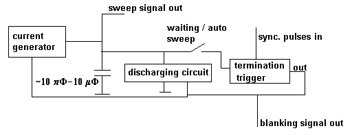
The current generator provides a stable current, which charges the capacitor. The value of the capacitor, as well as the current value determine the sweep frequency. In typical instruments, this frequency changes from 0.5 - 1 Hz upto several hundreds kilohertz, providing the sweep speed from 1 sec/screen up to 0.5-1 microsec/screen. Since the charging current is stabilized, the voltage on the capacitor rises up by linear law. When sweeper works in automatic mode, the termination trigger is connected to the capacitor and when the voltage exceed some level, trigger produces a reset signal, which opens the discharging circuit with simultaneous stopping of current generator. Now, the capacitor discharges quickly. When the voltage on it falls down, termination trigger turns the reset signal off and the new wave is generated.
Sync. pulses are also affecting the termination trigger, but with the regard of reset threshold. In a waiting mode, the generating loop is broken by the switch and only external synchronization impulse can start the sweeping. The signal from the termination trigger is used also for blanking of the CRT beam while capacitor is discharged. Otherwise, the main image will be overlapped with the non-linear second one, formed by the back path of the beam.
'X' final amplifier
This block is usually almost the same that is used in a signal channel. Signal level at the output of the sweeper is rather high (several volts), so not much gain is required. The requirements for bandwidth are not so strict as in signal channel, so more gain per stage is allowable. Therefore, this amplifier consists typically on differential emitter-repeater with one-two amplification stages (made by differential design).
3) Some words about cathode-ray tube.
There are plenty of types of such devices. They differ according to the number and functions of electrodes, voltages used in operation, maximal operating frequency, principles of focusing etc. For common purposes and for not very high frequencies, usually the simplest type of CRT is used. Such tubes are rather cheap, have minimal number of electrodes and provide all necessary functions. The only their disadvantage is that they have to work with grounded anode, and many others electrodes must have very high potential relative to the ground. This makes the feeding rather complex. Also, such voltage distribution does not allow to feed the blanking circuit from common power supply. On the next picture there is a schematic diagram of such type of CRT with all accompanying circuits.
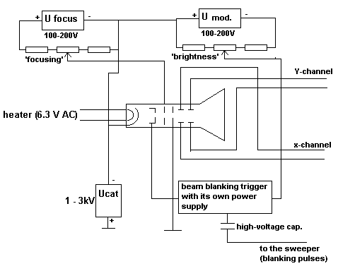
The second anode is grounded, because the tube work properly only if the voltage between it and deviation plates is low. That is why, cathode has very high (several kilovolts!) negative potential. Since for proper focusing and brightness the first anode and modulator must have potentials, which are several hundreds volts away from cathode's potential, they also bear huge voltage. For it's feeding, two additional power supplies are needed, which usually use the same secondary winding of transformer. It should be noted, that insulation requirements for this transformer, as well as for wires for these circuits, are very high due to high voltage.
Since the simple CRT does not have any special electrodes for beam blanking, modulator is used for that purpose. If the beam is unblanked, special trigger does not have potential between it's outputs. While blanking, this trigger supply additional 20-30V into the modulator circuit causing decreasing of the brightness to zero. The trigger is controlled by the sweeper trough high-voltage capacitor (DC connection is not possible here!).
As it can be seen, the feeding of CRT is rather complex and require many well-insulated independent windings on the power transformer. Advanced types of CRT can be used with grounded cathode. This makes their use much more simple and reliable. Also, some of them have special blanking electrodes which makes the use of blanking trigger unnecessary. But such CRTs are more rare and expensive.
My simple oscilloscope itself: construction
So, after a long theory let's start to describe what was declared in the title of this long page....
Signal channel
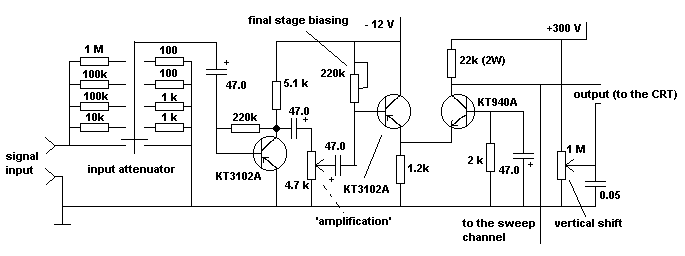
Signal channel of my instrument consists on only three stages. But inspite of it, the sensitivity is quite high - 5 mV is enough to deviate the beam on 1/3-1/2 of screen's height. Unfortunately, such big amplification per stage yielded narrow bandwidth - the amplifier works fine below 200-300 kHz, and beyond 1 MHz the response is closed to zero. But this is enough to be able to work with AF signals and analyze many kind of digital equipment. Also, to simplify the construction, the stages are coupled capacitively. This eliminates the possibility to monitor DC components of the signal, but it is still affordable for first time.
The diagram of 'Y'-channel is on the next picture. Monitored signal is passed first trough input attenuator, which has division coefficients 1:1, 1:10, 1:100, 1:1000 and 1:10000. This is NOT FREQUENCY-COMPENSATED DEVICE, and the compensated attenuator would be fine instead of this. After the attenuator, the signal goes to the common-emmiter preamplifier, which has at least 30-35 dB of gain. Since the input attenuator has very limited number of positions, additional ability to control the gain of the system is required here. The variable resistor after the first stage serves for it, providing smooth stretching the image in vertical dimension. The second and third stages are forming one 'combined' ('cascode') amplification stage on two transistors. The first one (KT3102A) serves as a emitter-follower and the second one works in common-base mode. The second transistor performs main amplification of the signal and is fed from high-voltage power supply (300 V). This allows to get minimum 200 V of undistorted signal.
Since the stage is connected directly to the CRT, internal tube's capacity shrinks the bandwidth. The stronger is collector current, the higher is output power, the larger is bandwidth. But the current is limited by power dissipation, and i have chosen after long experiments 'critical' value of loading resistor (22 K), which provides maximal bandwidth with retaining of reliable working of this stage (with a small heat sink). From the collector of the last transistor the signal goes to one deviation plate of CRT and to the sweep channel for synchronization purposes. The DC potential of the second one is controlled by the variable resistor in order to provide vertical image shift. The only semi-variable resistor in the base circuit of the first transistor is used to carefully bias the whole stage in order to get maximal signal at the output without significant distortions.
Sweep channel
The sweeper in my first 'oscilloscopic tester' (I suppose, it is most adequate name for such type of device) is incredible simple. I must confess, that the idea was totally mine one, and when i saw, that it really worked, i was greatly surprised...
The idea of working of the oscillator, which produces a saw-shaped wave is the following:
It is known, that capacitor, connected to some power supply, charges by non-linear (exponential) law, in first moment very quickly and then - slows down. But the initial part of this curve is almost linear, and if you keep the capacitor voltage low, you can use the charging process as the source of lineally rising signal. To have a reasonable level of such signal with reasonable non-linearity, you must use rather high voltage on the supply . Also, introducing different resistors in the circuit, you can vary the speed of charging in very wide limits. The same result may be also achieved by changing the capacitor.
In our unit we have already a 300 V power supply. So, if we connect it to the capacitor through some resistor, and provide charging of the cap. to the voltages below 10 V (for example), this will be a simple though good sweep generator.
Next, we need some device, which will reset the voltage on the capacitor to zero after it exceed some level (U1), and also some device, which will be driven by synchronization signal and will reset the sweep if the voltage on the capacitor exceed synchronization threshold (U2, U2<U1) (see principles of synchronization).
My solution is following: in parallel to the capacitor, a thyristor is connected. Its driving electrode is connected to the simplest voltage stabilizer on one zener-diode with breakdown voltage about 10 V. Until capacitor voltage is below 10 V, thyristor is closed. Then it opens and discharges the capacitor though itself. After it, it closes again and process repeats.
To ensure synchronizability of the sweeper, additional transitory is connected in parallels with zener diode. If it opens by means of synchronization signal, it is equivalent to zener diode opening, which causes sweep reset. Such system, being too simple to be excellent, still provides reliable sweeping and synchronization at frequencies below 200 KHz. Above, its performance goes down, but at the same frequency signal amplifier has the top of its bandwidth, so everything is 'matched' here. Schematic diagram of practical implementation of the words said above is here:
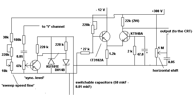
I think, that sweeper schematics is clear after a long explanations. By the 15 (!) different capacitors it provides sweeping with frequencies starting from several hertz upto 25-30 KHz, which is enough for this instrument. Generator itself provides 10 V of signal while unsynchronized and about 3 V when synchronized. Final amplifier has the same schematics as in signal channel (see above).
73!, Valentin Gvozdev , RU3AEP.