The
simple 7MHz CW transceiver
made with Motrola MC3362P by JG1EAD
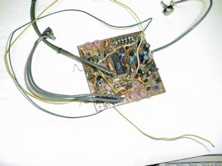
The 7MHz CW transceiver made with
MC3362P. I made a 7MHz CW transceiver by using the IC for the narrow band
FM double super receiving circuit, MC3362P. I intended to make a transceiver
for 10MHz band in the beginning. But, I was worried by the neighboring
spurious signal which wasn't expected, and I changed the plan. I changed
frequency to 7MHz band, and continued the production, and completed this
transceiver. The CW transceiver made by MC3362P was introduced to the
QST journal of December, '90 and January, '91 as well. (The article of
the translation of selected passages appeared in August, 91 issue of the
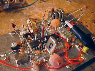
JA-CQ journal as well.) Because 2 set of double balanced mixers and local
oscilators are built in this IC, it is suitable for the single super heterodyne
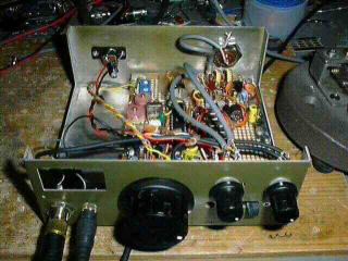
receiver of SSB/CW. I made the whole circuit scale compact by using the
1st mixer of the receiving circuit as the mixer for the transmission as
well. I am only using 2 transistors of the transmitting output stage,
1 FET of the reception AGC, NJM386(second source of LM386) and 4 transistors
such as the transmitting-receiving switch, except for MC3362P. But, though
it is very much disappointed, it seems to finish the production of MC3362P
by the end in 1998. (The Motrola company recommends MC13135 as the substitut.)
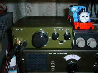
I included this transceiver into the case of 'P-7' which
was kit of the Mizuho company. As for being reflected by the photograph
of the upper front panel, a slide switch under that is a power switch
with a stereophonic headphones jack, a key jack, a VFO knob, RF gain,
AF gain from the left. It is the power supply connector of DC6 - 9V and
a M-type antenna connector that it is reflected by the photograph of the
rear panel.
 The 7MHz CW transceiver made with
MC3362P. I made a 7MHz CW transceiver by using the IC for the narrow band
FM double super receiving circuit, MC3362P. I intended to make a transceiver
for 10MHz band in the beginning. But, I was worried by the neighboring
spurious signal which wasn't expected, and I changed the plan. I changed
frequency to 7MHz band, and continued the production, and completed this
transceiver. The CW transceiver made by MC3362P was introduced to the
QST journal of December, '90 and January, '91 as well. (The article of
the translation of selected passages appeared in August, 91 issue of the
JA-CQ journal as well.) Because 2 set of double balanced mixers and local
oscilators are built in this IC, it is suitable for the single super heterodyne
receiver of SSB/CW. I made the whole circuit scale compact by using the
1st mixer of the receiving circuit as the mixer for the transmission as
well. I am only using 2 transistors of the transmitting output stage,
1 FET of the reception AGC, NJM386(second source of LM386) and 4 transistors
such as the transmitting-receiving switch, except for MC3362P. But, though
it is very much disappointed, it seems to finish the production of MC3362P
by the end in 1998. (The Motrola company recommends MC13135 as the substitut.)
The 7MHz CW transceiver made with
MC3362P. I made a 7MHz CW transceiver by using the IC for the narrow band
FM double super receiving circuit, MC3362P. I intended to make a transceiver
for 10MHz band in the beginning. But, I was worried by the neighboring
spurious signal which wasn't expected, and I changed the plan. I changed
frequency to 7MHz band, and continued the production, and completed this
transceiver. The CW transceiver made by MC3362P was introduced to the
QST journal of December, '90 and January, '91 as well. (The article of
the translation of selected passages appeared in August, 91 issue of the
JA-CQ journal as well.) Because 2 set of double balanced mixers and local
oscilators are built in this IC, it is suitable for the single super heterodyne
receiver of SSB/CW. I made the whole circuit scale compact by using the
1st mixer of the receiving circuit as the mixer for the transmission as
well. I am only using 2 transistors of the transmitting output stage,
1 FET of the reception AGC, NJM386(second source of LM386) and 4 transistors
such as the transmitting-receiving switch, except for MC3362P. But, though
it is very much disappointed, it seems to finish the production of MC3362P
by the end in 1998. (The Motrola company recommends MC13135 as the substitut.)
 I included this transceiver into the case of 'P-7' which
was kit of the Mizuho company. As for being reflected by the photograph
of the upper front panel, a slide switch under that is a power switch
with a stereophonic headphones jack, a key jack, a VFO knob, RF gain,
AF gain from the left. It is the power supply connector of DC6 - 9V and
a M-type antenna connector that it is reflected by the photograph of the
rear panel.
I included this transceiver into the case of 'P-7' which
was kit of the Mizuho company. As for being reflected by the photograph
of the upper front panel, a slide switch under that is a power switch
with a stereophonic headphones jack, a key jack, a VFO knob, RF gain,
AF gain from the left. It is the power supply connector of DC6 - 9V and
a M-type antenna connector that it is reflected by the photograph of the
rear panel. 